Friday, 27 March 2015

Computer Installation

Hello and welcome back to post #9 of my blog on how I built my own in-car computer system.  It has been a while since I last posted, as I have had other commitments to attend to, however I have made huge progress and have mounted the computer in the car and have it in a working condition. 

Naturally, there was a lot of wiring that needed to be installed in order to get the computer working, so to keep things concise I won't go into detail about every terminal connection I installed. 

In order to save time on installation, I decided to run all of the wiring first before installing the computer. This worked quite well and saved me a lot of time.

Seeing that the head unit was replaced in the previous post by the touchscreen, An amplifier was required to drive the four satellite speakers. I found a second-hand one on Gumtree and bought it for $35, a good deal by any standards.

Second hand amplifier. It is old but still works without any issues.
Unfortunately the amplifier was designed in such a way that it has four RCA inputs; one to drive each speaker and it does not have internal bridging, meaning that four RCA channels are required to drive all four speakers. In addition to this I needed another two RCA outputs to drive my subwoofer amplifier. To solve this problem I made a trip to my local electronics store and bought four RCA single to double adapters and a couple of RCA plugs. I made two short RCA cables from the plugs and an old RCA cable to go from the adapters to the other inputs, and used the double adapters to allow another two inputs for the sub woofer. This is a temporary measure as I will eventually buy better amplifiers with built in pre-amps. 

I extended the wires from the factory head unit harness down under the font passenger's seat to where the amp is housed.

Wiring the power to all of the amplifiers was relatively straightforward. I have created a rough circuit schematic to show how power is delivered to the system as a whole:

Rough circuit schematic. The box on the far left is the passenger's side A-pillar where the wires are ran up to the roof.  The box above and to the right is the compartment above the glovebox where all the excess wires are stowed. The battery in the schematic is the auxiliary battery, the main battery is not shown. Also note that the earth connection for the main amplifier is missing. The two round dots forward of the pc are the two interior lights.
 Running the wires was simple enough, The passenger side A-pillar cover was removed along with the door seal and roof handles revealing plenty of room to run wires along the steel pillar up to the roof.

Passenger A-pillar with some of the wires installed


Compartment above the glovebox with some of the wiring installed. The fuse on the right protects and splits the wires to power the computer and the 4 channel amplifier.

in addition to the power wires, the following other cables were ran;

  • 2X 5M USB extension wires, one for the touch screen data and another for the OBD2 interface
  • 1X 3M HDMI extension lead for carrying the video signal to the screen. Note I used a HDMI to DVI converter to take a DVI signal from the computer as audio was not needed. I also used a HDMI female to female adapter to go from the male end of the extension cord to the male end of the HDMI plug from the screen's main wiring harness. 
  • 1X 5M 3.5mm stero to 2X RCA cable to carry audio from the computer to the amplifiers
  • 2X Signal wires for powering on the amplifiers (in schematic above). Note these come separately from the computer as the computer turns the amplifiers on once it has booted.
  • 1X 4 core wire for accessory switches on the console
  • 1X single core red wire for misc. accessories. This was not used
  • 1X mini coaxial wire connected to a magnetic antenna for the FM radio. Until I buy the adapters to adapt the factory radio to the USB receiver stick I am using a small antenna mounted on the roof above the passenger side door. 

 With all the wires ran it was time to make final preparations to marry the computer to the car.

Computer in console with the wireless bluetooth and wifi antenna (left) mounted


Computer and console ready to be mounted.
 With some help, the four screws were installed and the console mounted to the roof once more. This was a slightly difficult two person process as lining the screws up was tricky due to their vertical position.

Console installed. The hole at the from which the wires are hanging will be covered with houses the factory interior light.
Once the rest of the wires were connected the computer was ready for a first test. After a few small tweaks and cable management the computer was fully functional.

Unfortunately during testing an annoying problem occurred with the screen. One of the buttons on its front face caved in, resulting in it becoming unusable and the unit looking broken. In order to fix this I had to remove the screen from its brackets and take it apart in order to fix it. I took this opportunity to do a quick tear-down to see how it worked. After carefully unscrewing it and fixing the caved in button I took a couple of snaps of the main driver board. It turns out that the button had slipped off of the micro-switch that it normally rests against. The cause of this was probably the screen not sitting quite right in its bezel in the dash, resulting in the bezel applying pressure on the scree's bezel and forcing the button off the micro-switch.
Main driver board for the screen
After carefully reassembling the screen with locktite on the screws, I fastened the bracket onto it once more and readjusted its fit in the bezel so there was no pressure on it.  This should stop this from happening again.

The whole install of the computer took me one whole day starting at roughly 8am to finishing at 5pm.

With the computer Installed and functioning, The next stage is to work out the software side of things. I am still doing a lot of testing and configuring on that front. Until I have made a lot of progress and am happy with the way it is running. Bye and as always, thanks for reading.

Saturday, 21 March 2015

Screen Installation

Hello and welcome to post # 8 of my blog on how building my very own custom in-car computer system.

Today has been a massive day in terms of progress. With some much appreciated help, I have fitted the screen to my Patrol by building a custom bracket and trimming the factory bezel to fit the screen.

To start off with, I'll provide a list of the materials and tools used for the build. All materials were purchased from my local hardware store and are readily available.

Galvanized steel, note it is L shaped.


I used a long (roughly half a meter)  piece of 2mm galvanized steel pre-bent into a L shape. It turns out the spaced pre-fabricated round and diamond shaped holes would be a huge advantage later on.


For fasteners I chose 316 grade stainless steel M6 bolts, contact washers and locknuts. The bolts coming loose from vibration was a key concern for me so I decided to use contact washers for extra piece of mind. I also bought a small bottle of Locktite 202 thread lock and some stainless M3 washers (not pictured). In summary, the materials used for the bracket are:

  • 500X100X2mm Galvanized steel L-bracket
  • 4X M6 Stainless Steel Bolts
  • 8X M6 Stainless Steel Contact Washers
  • 4X M6 Stainless Steel Locknuts
  • 4X M3 Stainless Steel Washers
  • 1X Bottle of Locktite 202 Threadlocker


 The tools I used are:
  • Screwdriver (Philips Head)
  • Long fine tipped Philips head screwdriver
  • 10mm ratchet spanner
  • 10mm spanner
  • Drill & Drill bits
  • Hammer
  • Vice
  • Flat medium file
  • Round medium file
  • Angle Grinder w/cutting & grinding discs
  • Ozito rotary tool (cheaper alternative to a Dremel)
  • Ruler
  • Pencil
  • Bench vice
The challenge was to find a way to mount the screen in place of the after market double DIN form factor head unit. 

After market DIN head unit (note the two steel brackets that screwed in on either side of it are missing) and iIm holding it where it originally sat for the photo with one of my fingers.


Cavity where the head unit sat. The wiring on the right is for the switch for my reversing lights.


After some thought and planning, I decided not to not use the stand that came supplied with the screen as there are no solid places to mount it in the cavity where the head unit sat. Instead we made use of the four M3 screws on the back of the screen that are presumably there to fit a stand/bracket. 

The back of the screen with the four M3 screws. The black bracket in the centre is for the supplied stand and won't be used for mounting the screen in the car.

 To start off with, I cut off two pieces from the L bracket with the angle grinder and filed the edges to smooth them. In a huge stroke of luck, the spacing of the prefabricated holes lined up almost perfectly with the screw holes on the screen. After drilling out the holes to a slightly larger diameter, fitting the brackets to the screen was simple.

screen bracket without the holes drilled out to suit the M3 screw holes.

To secure the brackets to the vehicle, I measured and cut another section of the L bracket, then bent it flat using the hammer and vice. Then I drilled holes in the now flat plate to coincide with the holes that were originally used to mount the head unit.

Backplate mounted using the head unit holes. Note drilling extra holes for the two plastic locating pins was slightly tricky as marking them from behind was impractical.
After doing some mocking up and approximate measuring, I decided to bend the two brackets for the screen by 90 degrees and bolt them straight onto the backplate. Any small errors in spacing could be fixed by bowing the screen brackets in slightly to adjust the distance of the screen from the backplate. Tilting the screen at an angle to position it more perpendicular to the user was not necessary as the viewing angle of the screen is excellent. 

Screen with the two bent brackets installed. Note the holes on the screen brackets are drilled out to accommodate the M6 bolts.

After fitting the M3 washers and locktite to the screen bracket screws, It was time to mock up the screen on the backplate again using the plastic bezel for position reference. It became clear that the top two plastic slots that house the bezel clips were interfering with the screen's fit, resulting in a gap between the top edge of the bezel and the screen when installed. Consequently, the bottom part of the screen that houses the buttons, light sensor, ect was completely covered by the bezel. To rectify this I used an angle grinder to remove the inside bottom corner of each slot to allow the screen to snugly fit between the slots. Fortunately this did not interfere with the function of the bezel clips as the clips used the vertical sides of the slots to grip and not the corners. 

One of the plastic slots with the inside edge removed.


After this was done and the screen checked for fit again, it was time to position the screen and mark out the holes to attach the screen brackets to the backplate. This was a difficult two person process that involved one person holding the screen against the backplate, while the other positioned the plastic bezel in place to check the position of the screen, then adjusting the screen's position by hand until it was successfully aligned. Then a graphite pencil cut approximately 5mm long was used to reach in behind the screen and mark through the screen bracket holes onto the backplate. This was especially difficult as during this process the screen could not be moved and had to be held in place by hand.

After the holes were marked I used the drill to make four holes through the backplate. Then I removed the backplate from the vehicle, and bolted the screen onto it.

Once the screen was secured to the backplate, the whole assembly was then secured back onto the vehicle using the four factory screws originally used to secure the head unit. 

screen secured to the vehicle

Some final adjustment was done by using the plastic bezel for reference and the screen mounting was then complete. In order to make the plastic bezel fit back into the dashboard properly, some cutting was required. This involved using a combination of the angle grinder, flat and round files and dremel tool to take away material where necessary until a snug fit was achieved. Unfortunately when cutting the plastic bezel the angled corners of the bottom of the screen was not accounted for, resulting in a slight gap at the bottom corners. 

Overall the fit turned out to be quite snug, and the screen feels secure in place and won't move from vibration when the car is driving. I am quite pleased about the design of the bracket as it is just as easy to remove as the factory head unit, as it uses the same four screws to secure it to the vehicle. 

The final product with the screen fitted.

After the screen was fitted, it was time to prepare the computer and console for fitting to the car. Back at my workshop I removed the computer from its testing arrangement and screwed it back onto the console using the four large wood screws.

In order to manually power on and off and reset the computer (the computer's power supply has a configurable system that has an on and off delay based on a wire that will be connected to the accessory position on the ignition, a power/reset switch is required. I used a Carling rocker DPDT (Double Pole Double Throw) switch, so that using the single switch I can power on/off the computer or reset it (in the unlikely event it hangs or crashes).


DPDT Carling switch installed in the console's 6-switch holder. I will order a custom made laser etched labelled cover for the switch later.

After connecting the wiring for the power/reset switch, ground and crimping the terminals for the computer power, map light power and ignition signal I did some cable management.

Managed cables
That is the extent of the work for today, there are a couple of minor things to mount to the console such as the dual band bluetooth/wifi antenna for the computer and the GPS unit, then the console will be ready to mount to the car. 

Special thanks to my Dad for helping me with the screen bracket, you can't appreciate the help of your old man too much :)

That's it for this massive post, and as always, thanks for reading. 

Friday, 20 March 2015

Screen Testing and More Software

Hello and welcome to post #7 of my blog on building a custom in-car computer system. In the last post I discussed the different types of software used to give the computer various abilities to meet the requirements I set in post #1. This post will cover the software configuration of the touchscreen and optimizing the computer for in car-use.

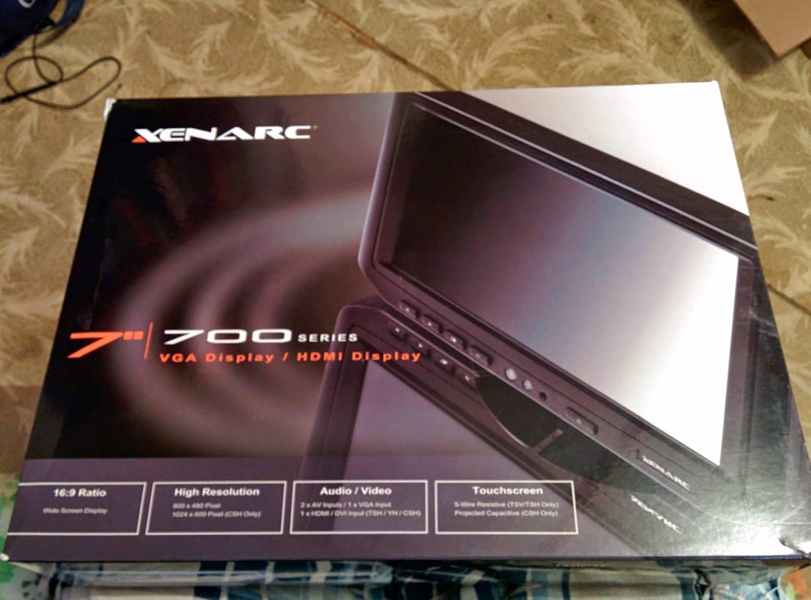
Good news, yesterday the touchscreen arrived!


For more specs see the link in the text above


 After unboxing the unit i was eager to test it with the computer.


Front view of the screen, the three round holes in the lower center area are for the IR remote control, ambient light sensor and power indicator LED, respectively.
 The unit is solidly built and overall feels like it is very good quality.
Rear view of the screen with the supplied malleable copper base attached. on the lower left you can see the area where the proprietary multi plug for the inputs and outputs goes, and the hole for the power connector.


 Straight away I noticed that Xenarc didn't skimp on the accessories. The unit comes with mains and 12V cigarette power adapters, a DVI to HDMI converter (which I will be using later), a driver CD, an extra U-bracket for securing the main pug to the screen (this will be handy to prevent vibration from loosening the plug), a full featured remote control and of course the stand and large main plug.


Other end of the main wiring harness plug. the connectors are: 3.5mm (for carrying audio to the inbuilt speaker), two RCA video plugs, an RCA audio plug (for mono audio), USB (for supplying the touch screen signal to the PC),  HDMI and VGA. If I had a bone to pick with this layout it would be that there were no dust-caps supplied for the plugs that won't be used (Ie everything except HDMI and USB).

Setting up the unit was as easy as attaching the stand and plugging in the main wiring harness and power plugs.


Testing set-up, the larger monitor in the background is no longer needed


 Adjusting windows to work properly with the display took a little bit of tweaking but overall it was a relatively simple process. Getting the resolution correct was somewhat challenging, as the monitor's native resolution of 1024 by 600 pixels was not supported by the Intel HD graphics chip build into the computer's CPU. However the screen supports many different resolutions, so to work around this I set the resolution to 1920 by 1080 (1080P HD) and then configured windows to have extra large (250%) Windows and text for easy use on the touchscreen. Interestingly when I tested the screen at 1280 by 720p resolution, windows disabled the mobile (RT) apps stating that the resolution was too low to run them. Strange.

I made the mistake of installing the touchscreen's supplied touch driver software, however this was not needed as the driver software (which comes with a fully featured software suite) emulates a USB mouse and therefore Windows would not recognize it as a touchscreen. This meant that all the touch features native to windows 8.1 would not work. To fix this I simply uninstalled the drivers and software suite and let windows automatically install generic drivers. From then on I had full multi touch support and access to the gesture based windows features.

Using the touch screen feels as responsive and smooth as as using a brand new Android or iDevice. Being capacitive, no pressure on the screen  is needed to register a touch, and multitouch pinching and zooming works flawlessly. I have no regrets in spending the extra money on this monitor over inferior resistive touchscreen technology though I do believe Xenarc has the monopoly as it was the only capacitive one I could find. 

The monitor's built in OSD (on screen display menu) has a few handy features, other than the standard brightness, color & contrast adjustments; you can disable the hardware buttons on the front of the screen, disable the extra (VGA, RCA, ect) Inputs, turn on or off the automatic brightness adjustment, and tweak many other features.

Testing the screen with Google Chrome was a pleasant surprise, as Chrome has inbuilt touch-screen support. Pinch to zoom, forward and back navigation by swiping and easy tab changing are all supported. 

Chrome running on the touchscreen
To improve its ease of use, I installed an extension called Speed Dial 2. Its basically a replacement homepage that lets you configure it to have links to your favourite websites with large icons (pictured above).


Here is the corsair link software that I discussed in the previous post. The iteration you see below is an early configuration I created for testing and monitoring the temperatures. Later I will set up various safety features such as automatic CPU temperature based fan control, high temperature warnings, automatic overheat shutdown and fan failure warnings.


Tomorrow I will start work on building a system to mount the screen in my vehicle, be on the lookout for more posts soon, and as always, thanks for reading.


Software Selection and Prototyping + Corsair Link

Hello again and welcome to post #6 of my blog on the design and build of my very own custom made in-car pc solution. A lot of progress has been made from the previous post, so  without further adieu let the build continue!

First thing's first. I have resolved the cooling issues once and for all. The two 40mm high performance fans have been installed in the case and the computer re-assembled. I have run stress tests and the thermal performance is more than satisfactory. However, the fans are extremely loud, so a system to regulate their speed and therefore noise level is required.

To regulate the fan speed I chose the Corsair link system. Corsair Link is a dynamic cooling system which has many applications in monitoring and control of internal pc components such as cooling fans, temperature sensors, RGB LED lighting and even real-time power consumption meters. The system is modular and highly expandable and versatile, which is perfect for my needs. I won't explain in detail how the system works, for more information see the link above. 


Link commander mini unit
Installing the corsair link commander unit was slightly tricky, as it was never designed to be used outside a computer's case. The link commander system uses a SATA power connector normally used to power hard drives and optical drives, and due to the very limited nature of the computer's power supply there were no spare sata power connectors. Luckily, I found a double sata power adapter cable in my workshop and used that as a workaround.

Getting the USB interface to work was another small problem. As mentioned earlier, the link system is designed to be used internally, so the USB communication cable has a motherboard header attached to it instead of your typical male USB type A plug. The motherboard of the car computer doesn't have two USB headers, and its only one is already in use for the two USB sockets on the front of the case. To rectify this, I simply chopped off the motherboard header and soldered on a male USB plug from an old USB cable.

The front of the PC in its final iteration. Note the USB cable plugged into the right hand USB socket is for the Corsair Link commander.

After a bit of cable management and sleeving I could refit the cases' original front cover plate.


I have a small complaint about the the PC case, specifically the build quality of the 8 pin plug & socket used for the power, ground, acc and amplifier remote on cables. For starters not all of the pins are populated on the computer side, but on the plug there a couple of seemingly random wires installed. I cut these off as there was no way to use them. However  problems started occurring during software testing as the other pins kept coming loose from the plastic plug & socket pieces, resulting in an unreliable and tempramental power connection to the PC. After unplugging and pushing the internal metal pins back in place only to have them pop out next time I plugged the plug in, I got fed up. I simply removed the plug and socket and ran heavy duty wires directly to the power supply, using male and female blade crimps instead. This an annoying and unnecessary modification, as the computer case should have been fitted with a better quality plug/socket!


Now comes the time for software installation. For the sake of not repeating myself and writing hundred page blog posts, I won't go into much detail about how I installed the software or why. I am not a software expert or a computer programmer but I do have an above average understanding of the windows operating system. So here we go:


To start the software prototyping and hardware testing phase I had the PC set up in my workshop using a standard LCD computer monitor, USB mouse and PS2 keyboard and some old desktop speakers. I powered the computer from a nearby parked car's battery, making sure to check the voltage periodically to ensure it could still start the car. 


The first software I installed (excluding the drivers for the audio, wifi, bluetooth, display, ect) was for the corsair link system. I downloaded it from the website and installed the latest version. There was some difficulty in getting the link commander to work properly but after restarting a couple of times and power cycling the commander unit the drivers initiated properly and I could start setting it up. The corsair link software itself is extremely customizable.


The next item was the GPS. I downloaded and installed the drivers using the link on the Ebay page from which I bought the unit. For GPS navigation software I used Navigator. It's a free GPS navigation suite that supports my GPS receiver. Installing it was a breeze, and it even had its own utility to automatically detect and use the GPS without any manual configuration. As a huge plus, it already has large touch optimized buttons which will come in handy for use on the smaller touchscreen. 

**11/15 Update: I am not using any navigation software on the computer as presently it is easier and better to use google maps on my smartphone. I was also unable to find good off-road navigation software as these days it comes pre-loaded with GPU units.**


Photo of the navigation software. Mu aplogies for the poor quality.


Finding an application for listening to FM radio through my USB dongle was slightly challanging. I settled on Radio Receiver, which is a free app that actually runs through the Google Chrome web browser's language (chrome doesn't have to be running for it to work) to achieve real time SDR (software defined radio). Basically this means that the USB stick receives the FM signal and relays it as a raw digital signal to the app, which then processes it into an audio signal and pipes it out of the computer to the speakers. There are a huge amount of apps out there for doing this, as it turns out the USB sick I chose (there are many out there similar to it) is capable of receiving a huge range of signals (including analogue and Digital TV, Digital radio and UHF signals used by aircraft for communications). For my application I needed something that was simple, only received FM radio, was touch friendly and could be activated with one or two taps, hence why I used a simple app rather than a full software suite.


**11/15 Update: In post #19 the dongle became faulty and I had to replace it with another one, which led to an interesting discovery.**

Getting Radio Receiver to work with the USB stick was problematic as I had some issues in getting the PC to recognize it. To get it working I used an utility called zadig. Zadig is basically a program that replaces the generic drivers for the USB stick with better ones to allow the USB reciever to work properly. After doing this and restarting the PC there were no more issues with Radio Reciever.  


Radio Receiver in action


For web browsing I use Google Chrome. Enough said. 


For power saving and general monitoring I'm using AI Suite 3. This is software that came with the motherboard and is handy for fan control (Used only for the CPU fan in my case as the case fans are ran by the corsair link system), and active power saving by dynamically limiting the CPU power consumption. This will be handy for extending battery life when the PC is left on wile the vehicle is parked. 

So far, all the software and hardware is working perfectly. Until my touch screen arrives there isn't much more I can do. Until then, goodbye and thanks for reading. 

Thursday, 12 March 2015

PC Peripherals

Hello and welcome back to my blog on building a custom in car computer. In the previous posts I discussed in detail how I designed and built a custom made console to house the miniature PC that I will be installing in my 4X4. I ran into some cooling issues on the way but I have taken measures to mitigate these problems. So, let the build continue!

So to meet the requirements I set in the first post, The PC needs to be able to have certain functionality added to it including:

  • -Display: Wile I used a desktop monitor for the initial testing, the PC will need a fixed monitor that meets the requirements for in car use, more on that later.
  • -Input: Obviously a mouse and keyboard are impractical and unsafe for use in a vehicle, so a touch-screen will be required.
  • -GPS: The PC needs to know where it is in order to run navigation software
  • -Radio: A FM radio receiver will be required so I can listen to my favourite radio station while I drive
  • -Internet: A high speed internet system will be required with high gain antennas to get mobile internet on the go. 
  • -Engine diagnostics: A module that plugs into the vehicle's OBD II port to read in real time engine statistics and clear fault codes. 
  • -Additional media controls (volume, play/pause, next/prev ect): For ease of use while driving.
First thing's first, in order to be able to use the computer, it will need a screen. However, there are several requirements that it has to meet in order to be practical for use in the car. They are:
  • Automatic brightness control. The screen must be able to adjust its brightness either based on the ambient light around it (Similar to what most smartphones and tablets do automatically), or have a dimming feature activated by turning the vehicle's park lights on (like most automotive head units) This is both a convenience and a safety feature as a screen that is too bright at night will disrupt night vision, and a screen that is too dim during the day is just plain annoying and hard to read. 
  • Capacitive touch input: This is a personal requirement, as capacative touch screen technology (Commonly found in all reputable branded smartphones and tablets) is far superior to resistive touchscreen technology. Not only does it provide much smoother and more responsive use, it allow for better screen viewing angles, multitouch and a glass coating that can be layered over the top for extra durability.
  • Automatic power on: The screen needs to turn on and automatically switch to the correct input channel when it receives power. 
  • Sufficient brightness for daylight use
  • Size - the screen is not too large or too small for the car's DIN bezel (By my measurements the active screen size has to be between 165-205mm  [6.5-8"] diagonal as the bezel can be cut to allow for a bigger screen)
  • Anti glare coating for easier readability in sunlight
  • Wide operating voltage range (roughly 10-18 volts to allow for voltage dips and surges)
  • Wide operating temperature range (roughly 10-50 degrees Celsius)
You will notice that many pf the main requirements listed above involve automation of some sort. I am a believer of the philosophy that automation improves safety by removing human error. During the planning and building of the computer system I have sought to include as much automation as possible with the exception of safety and redundancy (backup) features. This also makes my life easier as the end user of the system as it means I can focus more on driving the car and less on using the computer. 

The screen I chose that meets all of these requirements is the Xenarc 700CSH. This screen (while ludicrously expensive) is a solid industrial grade unit that supports touchscreen control VIA usb and has acceptable resolution for its size. After all, the screen is the component of this build that I will see and use the most. 

With the display and input requirements covered, it's time for the GPS:

I chose the latest and greatest in GPS technology, the BU353S4 (Which I have now received from the mail). This compact unit is not only IP rated to be splash-proof and dust proof, it has a handy magnetic base for attaching to ferrous surfaces (It conveniently sticks to the steel bracket built into the front of the roof console). Performance wise, it has the latest SiRF star IV GPS chipset at its core which is more than surplus to requirements for my needs. 

For the FM radio I chose a cheap and cheerful RTL232U based FM radio+ DAB USBdongle. This unit supports digital TV and radio as well, but as it turns out finding a FM-only dongle these days is almost impossible. I will need to find a way to adapt the external antenna plug on the dongle to my vehicle's coaxial plug to use it with the existing FM antenna later on. 

I still have not decided on a mobile internet router, as I will need to so some research on which system with which carrier will provide the best coverage at the best price. Until I decide on a solution I will use the hotspot feature on my smartphone. More on that in future posts.

I have plans to upgrade the PC later on with other peripherals, such as USB HD video cameras for 24/7 security/dashcam recording and a dynamic control system for on-board lighting systems. These systems will be fitted at a later date; right now I'm focusing on getting the car pc with the original requirements running perfectly.

As for the engine diagnostics, I have had no luck in the past trying to read fault codes from my vehicle's ECU. This is due to Nissan using a proprietary interface system known as Consult, which requires special licences and hardware to use. I am currently working around this problem and will post updates in the future. This peripheral system may stay on hold as I have plans in the works to re-power the vehicle with a different engine, which will use a different ECU and hopefully the standard OBDII protocols.

**Update 26/9/15**
I have integrated engine diagnostics into the computer, see posts #15 & 16.   

That's it for now, The next post should include the installation of the extra switch holder, the boxing up and re-installing of the computer into the vehicle and the planning and installation of the monitor into the car. I know this post probably wan't as interesting as the other ones (it certainly wasn't as illustrated), but more photos will come. Goodbye and thanks for reading. 


Tuesday, 10 March 2015

More Cooling Fixes

Hello and welcome to post #4 of my in-car PC Build!

Today I received the cooling fans I ordered from Newegg.com and have installed the 40mm fans in the case. As mentioned previously the 60mm fans did not get used in the build.
40mm super-high airflow fans (left), and 80mm high flow fans (right)
Before installing them, I tested the 40mm fans, and I have to say for such a small unit they pack one hell of a punch!. Despite being very noisy (The spec sheet lists them as 54.5dba), they move an amazing 24 Cubic feet per minute. I couldn't find the specs on the original case fan, but the model up from it that draws more current and therefore has a higher rotation speed and CFM, is rated at 8.6CFM. Therefore the airflow capability has been increased by a factor of 2.79.


Upgraded 40mm fan (left) next to the fan that came supplied with the case (right)

Upgraded fan (left), and factory fitted fan (right)
I have no doubt that these fans will provide surplus cooling capabilities to the PC. However, it comes at a price. As I mentioned earlier the fans are very noisy (They rotate at an impressive 13,000RPM or 1361.36 Radians/Sec for any physics/mechanics buffs out there) and emit a shrill buzzing sound, not ideal for situations when the PC will be used in quiet conditions (eg running as a FM radio when the car is parked). In order to reduce the noise level, I plan to fit a software/hardware solution to reduce the fan speed and therefore the noise. More on that in the coming posts.

I have made a final improvement to the PC's cooling system; I noticed the heat-sink for the MOSFETS was very loose and upon further inspection I realized that it was held on with two spring loaded screws, which were being compressed by the motherboard tray in such a way that the only thing facilitating thermal transfer between the MOSFETs and heat sink was a measly strip of thermal tape. This wouldn't do. I removed the heat sink and thermal tape and applied thermal adhesive to the MOSFETS (being careful not to apply too much) before replacing the heatsink and allowing time for it to set. 

That's it for this post, I'll write a new one as the project progresses. Thanks for reading.