Wednesday 18 November 2015

Wifi Hotspot Integration, UI Tweaks and Spintires :D

Hello and welcome to post #20 on my project of building a custom in-car pc and now also an infotainment and gaming(!) platform.

Today we decided to install a USB wireless dongle to add extra wireless networking capabilities to the car. One such use for these is creating an "ad-hoc" network where the car PC becomes the equivalent of a wifi hotspot/mobile LAN router. This opens up more possibilities and options for networking the PC and integrating it with mobile devices such as smartphones.

The USB Adapter in question
I fitted a TP-Link TL-WN727N USB 2.0 150MB/S wireless adapter. Its the lowest model TP link makes but I had it as a spare so i figured it couldn't hurt to try it.

After connecting it to the car (it uses standard windows drivers which installed automatically) to the computer we downloaded Wireless Adhoc Manager, which is an application which easily allows the user to create an ad-hoc network. It allows the user to set the SSID (the name of the wifi network) and password quickly and easily with no fuss.

One immediate use to improve the PC's usability is to connect my phone to the new wifi network and open Splashtop Remote HD to remote control the PC in real-time HD. When I buy a wireless or satellite transceiver for mobile internet anywhere this will allow setting up the car as a mobile hotspot.

One added advantage of having an additional wifi adapter (The PC now has 2) is that it allows devices to be connected to the TP-link while retaining its internet connection over my home wifi network.


For the windows 10 UI improvements, we did the following:

  • Change windows explorer default start-up page to "this PC" from "Quick access"
  • Removed the search button from the task bar to free up more space
  • Removed cortana from the start menu and rearranged icons
Finally, we installed Spintireshttp://spintires.com/.

Spintires opening video


Spintires is a challanging co-operative multilayer offroad driving simulator game set in 1980's soviet russia. The player can choose from over 18 different Russian trucks ranging from light 4X4 scout vehicles to lumbering 8X8 trucks. The objective to the game is to drive from a garage to logging stations, pick up lumber and deliver it to an objective whilst driving through extreme terrain such as mud, swamps, lakes, water crossings, beaches, forests and rocky hills. The trucks can be customized with various attachments such as fuel tanks, repair kits (trucks incur damage if you drive them too rough). 

Spintires is only available on PC through steam (I installed it prior to the game)

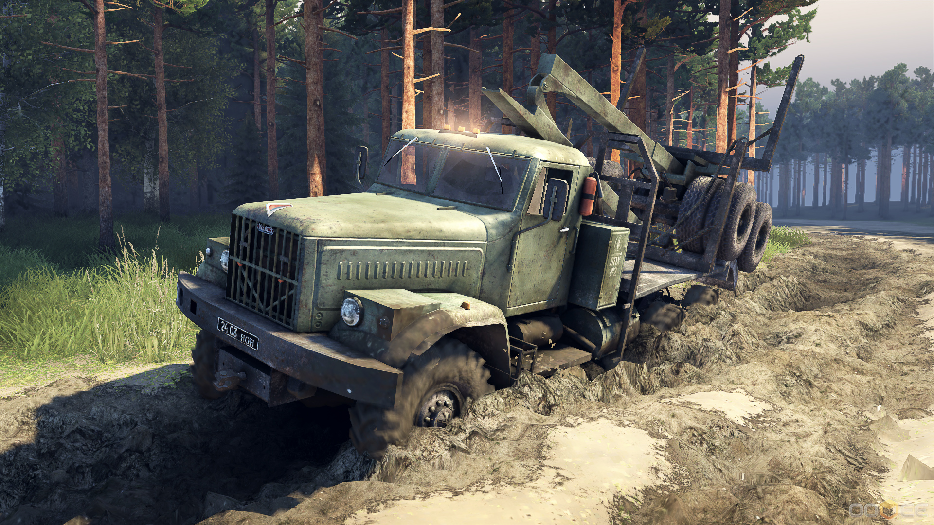
In-game screenshot a truck slogging its way through mud
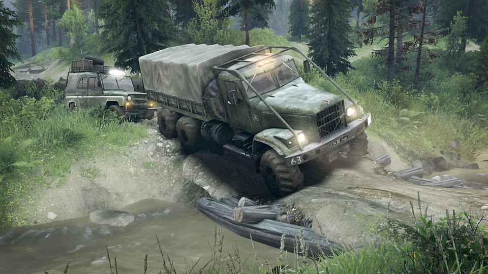
A truck edging its way across a rickety bridge. The level of detail in the game is impressive; the bridge flexes and creaks, threatening to collapse as the truck rolls over it.
Unsurprisingly the PC with its 4th generation Intel core i3 processor clocked at 3.8ghz and no graphics card (It has onboard intel HD4000 series graphics built into the CPU) the computer struggled hard to run the game at full settings, stuttering at roughly 10FPS. After some tweaking of the settings (720P resolution, Shaders set to low, Draw distance set to medium, Grass density low, Level of detail medium, Mud detailization on and most of the check boxes turned off

Spintires graphics settings menu. Note this is not my screenshot, I don't know how they managed to run a 6000X1080 resolution.


I can now proudly call my computer system a fully fledged multimedia and gaming platform, along with its other titles. As an added bonus I'll never get bored if I'm stuck waiting in my car again :). Goodbye and thanks for reading.

TLDR: I can no go 4wding from within my 4wd. I call it fourbyception :D 


Monday 16 November 2015

Rear Programmable Keys, FM Fixed and Keyboard Installed

Hello and welcome to post #18 of my project on building an all in one in-car PC based multifunctional system.

Roughly a month ago the FM tuner app Radio Reciever in my Patrol started displaying an error when started stating it could not connect to the FM tuner dongle. I suspected the tuner to be faulty due to the poor FM signal I experienced in previous posts, so I ordered another almost** identical tuner from Ebay. 

After doing some research and popping the new tuner open when it arrived I made an interesting discovery. The older black dongle had the older R820T tuner chip (This is the part that the antenna is connected to and which selects the desired frequencies then feeds them to the RTL2832U which does the demodulation and interfaces with the PC). 

The R820T (older model) tuner chip that was housed in the black dongle
At first the dongles appeared identical, save for arbitrary differences like a white LED and different brand capacitors. It has the critically important RTL2832U but crucially it has slightly different (by one character) R820T2 chip which the manufacturer claims has a 6db lower noise floor than the the previous model. The bottom line is it can pick up signals better using smaller antennas. I found proof of this when I got an almost perfect signal while driving with the cheap telescopic adapter it was supplied with taped to my car's snorkel, whereas the older black dongle would struggle to get signal through the car's factory FM optimized antenna when it was fully extended.

I have relocated the FM tuner into the electronics bay (above the glovebox) and I will get a friend to redo the coaxial wire (which incidentally originally ended in the same area) and shorten it to suit the adapter to restore function with the factory antenna.

Aforementioned crappy antenna attached to my snorkel
Moving on to the next item - It was decided between my friend and i that we needed a better way to control the PC in case it needed software maintenance and configuration while away from home. The old solution of carrying an ancient Microsoft PS2 keyboard and USB mouse under the drivers seat was not practical. I had the idea of attaching a wireless keyboard to the back electronics bay door (located above the glovebox) so that when it was opened the keyboard swung down on with the door resting comfortably on the user's knees. This idea was further improved by changing the keyboard to a wireless one with a built in trackpad. 
Electronics bay door. I made it by cutting out the plastic plating that was behind it and adding a lock salvaged from a scooter seat and attaching it to the car once more with hinges. There is empty space (The safety pack model of the car housed an airbag here) which in the last post I filled with a switched power distribution system.


A quick online search to find a compact keyboard that would fit on the compartment door and a trip to my local electronics stores later and we had a unit that fit perfectly. It was necessary to grind off the plastic studs protruding from the inside of the door with a Dremel. After that we simply attached the keyboard with some Velcro tape for easy removal.

Keyboard/trackpad mounted in place on the electronics bay door.

However, Due to the large amount of USB devices (GPS, FM, USB3 hub, Touch screen, ECU diagnostic link, Volume knob, Bluetooth 4.0 dongle and the Wireless keyboard/trackpad dongle), only one free port remained. Therefore it was necessary to fit another hub which would be dedicated to running system infrastructure. To achieve this I bought a 7 port powered USB hub.then cut the DC power plug from the mains transformer and ran the wires directly into a multi-purpose DC-DC step down converter converter (The same model converter as the ones I originally used to power the old centre console USB charging set-up, except only one was used to avoid the interference issues). Then I wired the converter in parallel to the screen as I want the hub to only be powered when the computer is running (Ie the screen is on). 

7 Port USB2 hub with the new blue FM dongle connected. I chose the metallic case type hub as this design has proven durable for me in the past


Luckily running another 5m USB extension cable was not necessary as we simply used the one that was already there for the volume knob then connected the knob to the hub. I connected the 2.4ghz dongle for the keyboard/trackpad, and an extra 5M USB2 extension which I will explain later. After that we mounted the DC converter (now acting as the USB hub's power supply) in a small project box and secured it to the hub with double sided tape.

Power supply box. Note the 5VDC cable running to the USB hub which is attached underneath. 
Then the whole unit was attached to the side of the SPDS with velcro tape for a neat finish.

Hub and its power supply in its final position in the electronics bay.

For the final modification of this post, we decided to install the X-keys stick that I had ordered a few weeks previously. X-keys is a class of fully programmable LED backlit keypads designed by PI Engineering. The model I bought is the XK-4, which is a row of four programmable keys. I figured I could find a use for them somewhere in the vehicle. We ended up using it as a mounted remote control for the PC's media functionality. Being limited to four buttons (I have an XK-8 on order to mount up front for full media control), we chose to assign Volume up, Volume down, Play/Pause & Next track to the buttons. 

XKeys Macro Software
Before fitting the keys to the vehicle, we first programmed it by activating the hardware programming switch on the keys themselves, then using a laptop and the MacroWorks software which is downloadable for free on PI's website. This was a learning experience for us both, but we were both very impressed with the versatility of both the macro software and the keys themselves. 

The keys are able to operate in two modes: In Software Mode the MacroWorks software must be running in order to receive the button press signal from the keys, then execute the assigned macro(s) in windows. This is the most versatile mode and it allows full functionality, and I do mean full. There are thousands of different macros and functions that can be assigned to the keys, including keystroke macros and application specific macros, eg iTunes media library controls like play & pause. 

In Hardware Mode the onboard micro-controller does all the work. Keystrokes (but not software macros as the unit can only emulate a keyboard) can be carried out and the LED backlights programmed to do different things in response to a key press & release. This mode is used for legacy support on non-winows devices (eg android phones, linux, and everything that supports a USB keyboard) as no software is require for the keys to funciton.

We decided on a place in the back of the vehicle that is out of the way to mount the switch. The position is intended to prevent accidental pressing of the buttons by cargo or loose objects, and to be in a convenient place for the user to reach.

A wider shot showing the position of the keys
The place we decided on was both easy to reach when the back door is open, and also when sleeping in the back with the bed installed, while not protruding in an easy to knock place. 

To install it we ran a 5M USB2 cable from the new 7 port hub along the door sills then through the cargo area. The bolt to the right of the keys was removed and the USB cable fed down between the two trim panels. The excess cable was neatly bundled up and tucked into the removable cover that was originally intended for accessing the tail light bulbs (this seldom gets used to do the LED conversion I did on the car). Overall a neat installation that adds a bit more customization and flare to the project.

Installed keys. Note they are supplied with a sheet of pre-cut icon & letter cards as well as a blank sheet to print your own.
I have made progress on installing a system to synchronize my music and playlists, more on that in the next post. As always, thanks for reading.


Switched Power Distribution & Protection System

Hello and welcome to post # 17 on building a custom car computer. This post is long overdue so I'll get straight into it:

Due to the large amount of 12V DC accessories and devices of all different shapes and current ratings I have installed in my vehicle, there was a large amount of messy wiring taking up the space where many of the power supply and various signal wires run through the firewall (the only two openings on that side were jammed full of wires!) I decided to design and build a safer, more reliable and easier to fix system.

Messy wiring from the computer & various  power circuits.


My solution is the Switched Power Distribution & Protection System, or SPDS for short. It is divided into two modules stacked on top of each other and Its purpose and function is threefold:

1) Provide a high current link directly back to the auxiliary battery for running devices intended for use from that battery. This was done by using industrial grade 1 gauge wire ran directly back to the 100A breaker in my engine bay, which is in turn connected to the battery via a similar cable. The SPDS end runs into a gold plated terminal block (housed in the  distribution & protection module) where it splits into different sized wires to power various areas of the vehicle.

1 Gauge battery cable running into the distribution block.
There is also an additional two wires run out of the PD&PM from the terminal blocks and into two high current fuses. these power the four channel and sub-woofer amplifiers.

2) Provide a high-current and reliable platform for improving switching options on the PC. Two issues arose with the original design, which turned the PC on when the key was set to the accessory position in the ignition barrel, and turned it off after a one minute delay when the key was removed. 

The first was that it posed a security risk in situations where I wanted to leave the computer on but wanted to lock the car, and was forced to leave the car unlocked as the key had to be in the ignition (EG when I use it for music while working on the car and go inside for a break). 

The second was that in situations when I was driving and didn't want the computer to keep automatically turning on (the hard power button kills the computer when held for 3 seconds but it turns on again as its PSU is configured to keep sending an on pulse (the equivalent of someone pressing the power button again) if the key is in the accessory position. The latter function is achieved by simply adding a switch between the accessory wire and PC.

To do this I used three relay switches. The relay labelled illumination is switched by a wire from the park lights. It acts as an isolator between the main and auxiliary batteries so that various devices can be switched on by turning on the park lights without draining the main battery. This is irrelevant for PC functionality however it was installed to run the auxiliary running lights built into my Hella Luminator LED driving lights as it was more convenient to wire them to a relay, switch and then the auxiliary battery then run a power wire across the dash and to a high current park wire and switch.

Relay module
The relay labelled screen (far right) is turned on by a switch in the centre console labelled "Screen Power". it is powered constantly from the distribution module, which turns on when the key is moved to the accessory position. This acts as an isolator between the main and auxiliary batteries so that the turn on signal to the PC (this is a +12V signal which signals the PC to turn on, similar to the remote turn on wires found on automotive amplifiers) can be activated at any time simply by flicking the rocker switch, regardless of key position. If the key is on than this will have no immediate effect.

The relay labelled power is turned on by a wire that is connected to the cigarette lighter socket. It switches on a high current connection from the distribution module to power various devices around the vehicle that only need to be running when the key is in the accessory position, eg extra cigarette lighter plugs.

finally,
3)Put devices and systems on different circuits and protect them with automatic circuit breakers.

These are switches that protect  the wiring by automatically opening when a certain amount of sustained current passes through them, eg if a short circuit occurs. These are vital for redundancy as they do not require changing of single use fuses and can be reset on a whim. The configuration of the circuits and their rating is as follows (from the top down):

Distribution & Protection module
1)
Rating: 30A
Area Powered: Overhead Console
Connected Devices:
  • Car Computer
  • Roof Console Lights
Additional Affected Devices & Systems on Failure:
  • Amplifiers will not turn on (Remote turn on signal runs from this circuit).
  • 7 Port USB Hub
  • PC Screen

2)
Rating: 30A
Area Powered: Rear Barn Door
Connected Devices:
  • Rear panel fuse block
Additional Affected Devices & Systems on Failure:

  • Reverse/rear lights
  • Rear cigarette lighter socket (Beware if fridge is connected)
  • Rear USB Charging sockets X2
  • Rear table strip lighting

  • 3)
    Rating: 15A
    Area Powered: Centre Console
    Connected Devices:
    • CB Radio
    • Centre console USB hub Boost power
    • Centre console floor light

    4)
    Rating: 15A
    Area Powered: Unsure
    Connected Devices: Unsure

    To construct the modules I bought two small project boxes that can be disassembled by hand by pulling off the end plates. I drilled holes in the corners of one side of each box, then fitted metal standoffs and screws to hold them together. As an added bonus the spacing keeps the modules held securely in place in the electronics bay without the need for fasteners.

    Fastening the two halves together
    I mounted the components in the boxes with stainless steel screws, spring washers & nuts then crimped the wiring together.
    Adding components
    Connecting components with suitably rated wire


    . The system took a whole day's work to build but will be worth it for the safe and reliable operation of equipment and systems on my vehicle. Keep an eye out for my next post and as always, thanks for reading.